Recipe Change Using PLC
Overview
This guide outlines the process for changing inspection recipes in the OV20i camera system using PLC logic. Recipe switching allows you to configure different inspection parameters and criteria for various parts or processes without physically reconfiguring the camera. Each recipe contains specific inspection settings, and switching between them enables flexible automation in manufacturing environments.
The recipe switching process involves a coordinated handshake between the PLC and camera, ensuring that recipe changes occur safely without interfering with ongoing operations.
Prerequisites
Before implementing recipe switching functionality, ensure the following requirements are met:
- OV20i camera connected to the PLC (see Connect to PLC (Ethernet/IP, PROFINET)).
- PLC programming software (e.g., Studio 5000).
- The desired recipes must be pre-configured and stored on the camera
Logic Example
The recipe switching logic follows this sequence:
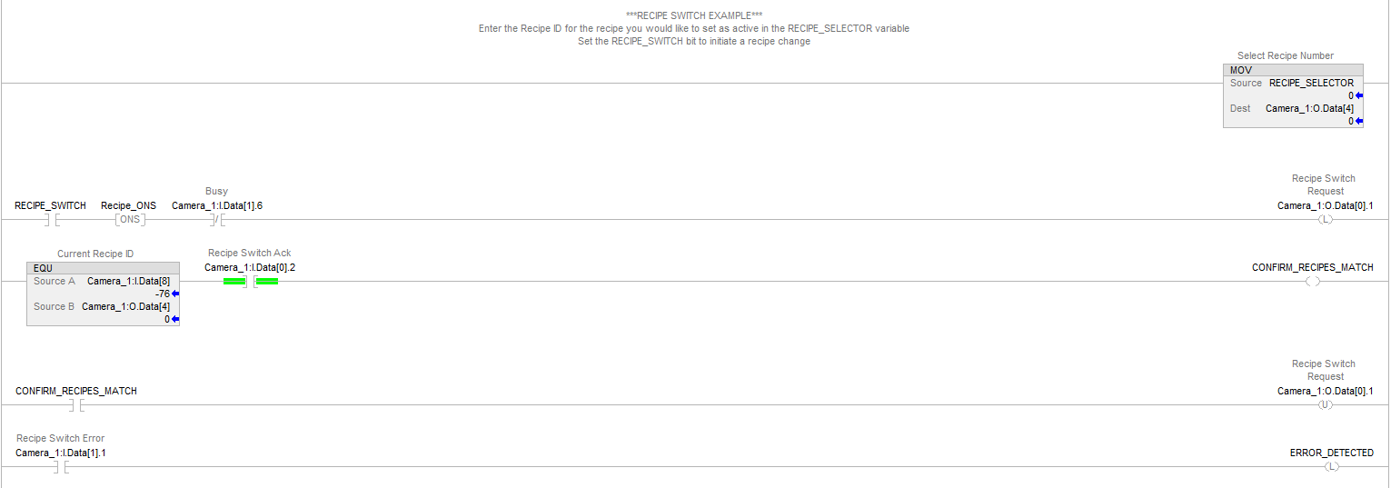
Step 1: Set Recipe Number
MOVE [Recipe_Number] → Camera_1:O.Data[4]
Transfer the desired recipe ID from your PLC tag to the camera's recipe selection register.
Step 2: Initiate Recipe Switch
[RECIPE_SWITCH] → [Recipe_ONS] → Camera_1:O.Data[0].1
Use a push button or control signal with a one-shot rising edge to trigger the recipe switch request.
Step 3: Monitor Camera Status
NOT Camera_1:I.Data[1].6 (Busy Signal)
Ensure the camera is not busy processing before initiating the switch.
Step 4: Latch Switch Request
Camera_1:O.Data[0].1 (Latch ON)
The recipe switch request bit must remain high until acknowledged by the camera.
Step 5: Verify Completion
Camera_1:I.Data[0].2 (Recipe Switch Ack) AND
EQ Camera_1:I.Data[8] Camera_1:O.Data[4] (Recipe Match)
Wait for both camera acknowledgment and recipe ID verification.
Step 6: Reset Request
Camera_1:O.Data[0].1 (Unlatch)
Clear the recipe switch request bit after successful completion.
Step 7: Error Monitoring
Camera_1:I.Data[1].1 → Error_Detected
Continuously monitor for error conditions during the process.
Timing Diagram
The recipe switching process follows this timing sequence:
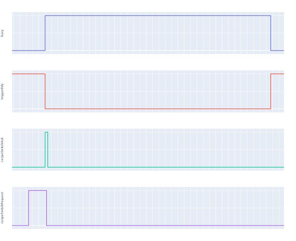
Signal Flow:
- Busy Signal: Starts low (inactive), goes high when process begins, returns low when complete
- TriggerRdy (Trigger Ready): Starts high (ready), goes low during operation, returns high when ready for next trigger
- RecipeSwitchRequest: Goes high to request recipe change, stays high briefly for system registration, returns low after acknowledgment
- RecipeSwitchAck: Goes high briefly to acknowledge the request, then returns low
Key Timing Relationships:
- The Busy signal tracks overall system occupation
- TriggerRdy indicates when the system can accept new trigger commands
- Recipe switch requests block triggering operations
- All signals must return to their idle states before the next operation can begin
This sequence ensures smooth transitions between operational states without conflicts.
Core Concepts
Recipe Management
- Recipe ID: Each recipe has a unique numerical identifier
- Current vs. Selected: The system maintains both the currently active recipe and the newly selected recipe for comparison
- Recipe Validation: The system compares recipe IDs to confirm successful switches
Signal Handshaking
- Request/Acknowledge Pattern: The PLC requests a recipe switch, and the camera acknowledges receipt
- Latching Logic: The request signal must be maintained until acknowledgment is received
- One-Shot Triggering: Prevents multiple requests from signal fluctuations or noise
Error Handling
- Error Detection: The system monitors for errors during the switching process
- Error Latching: Error conditions remain latched until manually cleared
- Process Blocking: Recipe switches block triggering operations to prevent conflicts
System States
- Idle State: System ready for new commands
- Busy State: System processing a recipe switch or other operation
- Error State: System has detected an error condition requiring attention
Best Practices
Safety and Reliability
- Always verify the camera is not busy before initiating a recipe switch
- Monitor error conditions continuously and implement appropriate error handling
- Use one-shot signals to prevent multiple unintended requests
- Validate recipe matches after switching to confirm success
Operational Efficiency
- Minimize recipe switch frequency to reduce system overhead
- Group similar operations under the same recipe when possible
- Plan recipe switches during natural breaks in production cycles
- Test recipe switches thoroughly before production implementation
Programming Guidelines
- Implement proper interlocks to prevent conflicting operations
- Use descriptive tag names for better code maintainability
- Document recipe purposes and switching conditions
- Include timeout logic for error detection in case of communication failures
Warning Notes
- Recipe switching blocks triggering operations - ensure timing coordination
- Do not leave recipe switch request high continuously - this will prevent normal camera operations
- Verify communication stability before relying on recipe switching in production
Summary of Key Signals
Control Signals (PLC to Camera)
| Signal | Address | Function |
|---|---|---|
| Recipe Number | Camera_1:O.Data[4] | Specifies which recipe to switch to |
| Recipe Switch Request | Camera_1:O.Data[0].1 | Initiates the recipe switch process |
Status Signals (Camera to PLC)
| Signal | Address | Function |
|---|---|---|
| Busy | Camera_1:I.Data[1].6 | Indicates camera is processing |
| Recipe Switch Ack | Camera_1:I.Data[0].2 | Acknowledges recipe switch request |
| Current Recipe ID | Camera_1:I.Data[8] | Reports the currently active recipe |
| Recipe Switch Error | Camera_1:I.Data[1].1 | Indicates error during recipe switching |
Internal PLC Tags
| Signal | Type | Function |
|---|---|---|
| RECIPE_SWITCH | BOOL | Initiates the recipe switch process |
| Recipe_ONS | ONS | Provides one-shot signal for switch initiation |
| CONFIRM_RECIPES_MATCH | BOOL | Confirms current and selected recipes match |
| Error_Detected | BOOL | Flags error conditions for operator attention |
Conclusion
Recipe switching in the OV20i camera system provides flexible automation capabilities while maintaining operational safety through proper handshaking protocols. Success depends on following the correct sequence of operations, monitoring system status, and implementing robust error handling.
The key to reliable recipe switching is understanding the timing relationships between signals and ensuring that the camera is not busy before initiating switches. By following the outlined procedures and best practices, you can achieve smooth transitions between different inspection configurations while maintaining system reliability and production efficiency.
Remember that recipe switching is a coordination process between the PLC and camera - both systems must be properly configured and communicate effectively for successful operation. Regular testing and validation of the switching logic will help ensure consistent performance in production environments.